
Flue terminal distance is a siting check: products of combustion must disperse safely and the terminal must not be blocked, damaged or too close to openings.
A boiler flue position needs a separate check against every nearby opening, gutter, corner and boundary. Identify the appliance and flue type, then use the relevant siting diagram and manufacturer instructions. A clear window distance does not prove that the whole position is suitable.
What the distance is trying to achieve
Approved Document J gives guidance for meeting the Building Regulations in England. It covers air supply, discharge of combustion products, carbon monoxide warning and protection of the building. For gas flue terminals, the distance check helps combustion products disperse to outside air and, where the appliance is balanced flue, protects the air intake. Other UK nations have their own building standards guidance.
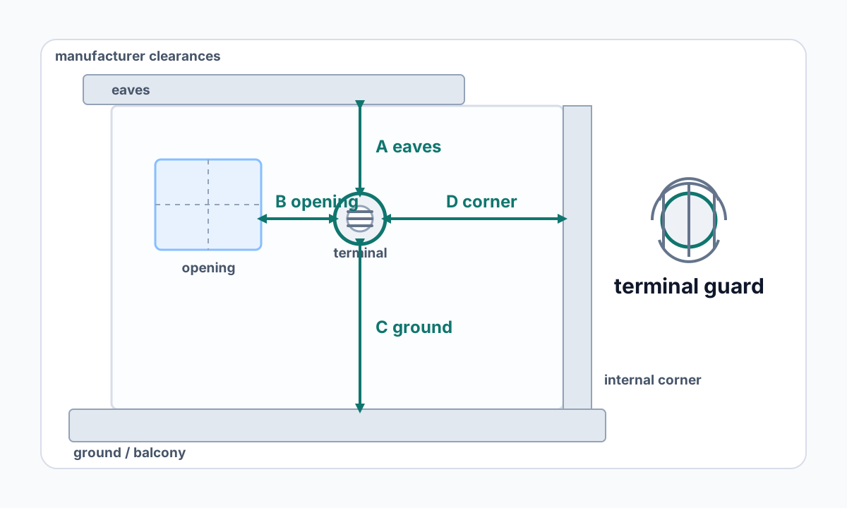
In the diagram below, A is the distance below the eaves, B is the horizontal distance to the opening, C is the height above ground or balcony level, and D is the distance to the corner. These letters identify our sketch only; use the letters and measurement points on the actual appliance’s diagram when looking up a clearance.
Why 300 mm is not the answer
You will see 300 mm in many domestic fanned balanced-flue examples, but it is not a universal boiler flue distance. Approved Document J separates locations such as below an opening, above an opening, horizontally to an opening, below eaves, from gutters, from boundaries, between terminals and above ground or balcony level. The required distance can change with terminal type, draught type and appliance input.
For example, the fanned balanced-flue column in the table to Diagram 34 gives 300 mm below, above or horizontally from an opening. The natural-draught balanced-flue column has different input bands. Do not transfer a number between those columns or assume it overrides the instructions for a particular boiler and flue system.
The checks to run in your head
- Identify whether the appliance/flue is room-sealed balanced, open-flued, natural draught or fanned draught.
- Find the relevant nearby feature: opening, eaves, gutter, drainpipe, corner, boundary, balcony, ground level, car port or another terminal.
- Check the appliance heat input band where the table uses it.
- Apply the manufacturer instructions and current standards before treating a generic distance as enough.
- Consider plume nuisance and wetting damage for condensing boilers even where the safety distance is satisfied.
- Fit a terminal guard where the terminal is vulnerable to contact, damage or blockage.
Openings and air vents
An opening is not only an openable window. Approved Document J also treats fixed openings such as air vents as openings for this purpose. The revision trap is measuring only to a window and forgetting the combustion-air vent, passive vent or built-in opening nearby.
Boundaries, corners and other terminals
Boundaries and opposing surfaces matter because products of combustion need space to disperse. Terminals facing each other, terminals on the same wall and terminals close to corners are separate checks. Each applicable clearance must be met; the physically nearest feature is not necessarily the one requiring the greatest separation.
A boundary alongside a terminal and a boundary facing its outlet are different arrangements. In the fanned balanced-flue column of Approved Document J’s Diagram 34 table, the starting figures are 300 mm alongside and 600 mm facing. Read the table notes and the appliance instructions too, including the conditions for any permitted reduction. A compliant boundary distance does not by itself resolve plume nuisance.
Flue terminals on or through a flat roof
A roof appears in three rows of the table to Approved Document J Diagram 34, and the row depends on where the terminal is. A wall terminal above a flat roof is row I, "Above ground, roof or balcony level": 300 mm for a balanced flue, natural or fanned draught, and for a fanned open flue. The natural-draught open-flue column is marked "Should not be used" in that row, as in every other wall row.
A vertical flue through the roof is row Q, "Above the highest point of intersection with the roof". The table gives a figure only for a fanned open flue: 150 mm. For a fanned balanced (room-sealed) flue it says to site the terminal in accordance with the manufacturer’s instructions, and for a natural-draught open flue in accordance with BS 5440-1:2008.
Row P, "From a structure on the roof", has an entry only for a natural-draught open flue: 1500 mm if it is a ridge terminal, and otherwise as given in BS 5440-1:2008, which BSI has since replaced with BS 5440-1:2023. Row P is marked N/A for balanced flues and fanned open flues, so take their distance from parapets, plant and other roof structures from the appliance and flue instructions.
A window or other opening in the roof is a separate check. Diagram 35 covers terminals next to windows or openings on pitched and flat roofs and shades a zone the flue should not pass through; drawn on a pitched roof, the zone runs 2000 mm below the window and 600 mm above it and to either side. Where people can reach a roof terminal or it could be damaged, paragraph 3.26 calls for a guard, as it does on a wall.
Common exam mistakes
- Memorising "300 mm" without checking which line of the table is being asked.
- Ignoring the difference between balanced, open, natural draught and fanned draught terminals.
- Forgetting air vents and fixed openings.
- Treating condensing plume nuisance as the same thing as minimum safety clearance.
- Omitting a terminal guard where the terminal can be touched, damaged or blocked.
- Using a generic diagram instead of the appliance manufacturer instructions for a real job.
A flue next to a gutter or downpipe
Below a horizontal gutter and beside a vertical downpipe are different positions. For a fanned balanced flue, the table to Approved Document J Diagram 34 gives 75 mm below a gutter, soil pipe or drainpipe, but 150 mm from a vertical drainpipe or soil pipe. Its note permits the latter to reduce to 75 mm for appliances up to 5 kW net input. That small-appliance exception is not a general boiler allowance.
Check the gutter or pipe material, the direction of the discharge and any protection or extension specified by the manufacturer. Heat and repeated wetting can matter as well as the measured gap. Do not move a downpipe or turn a plume deflector and assume every other clearance is still satisfied.
Worked clearance check: one pass does not cancel a shortfall
Suppose the applicable appliance instructions require 300 mm horizontally from an opening and 150 mm from a vertical downpipe. A proposed terminal is 350 mm from the opening but only 100 mm from the downpipe. The opening check clears its requirement by 50 mm; the downpipe check is short by 50 mm. These margins cannot be added or averaged.
The position needs reassessment against that appliance’s instructions. A plume-management kit may change which discharge or air-intake positions need checking, but it is not a universal way to waive a clearance. Use a flue arrangement approved for the appliance and check all of its relevant dimensions again.
Extract fans and open-flued appliances
Terminal position is not the only outside influence on an open flue. Approved Document J paragraph 1.20 explains that extract fans lower the pressure in a building and can make combustion products spill from an open-flued appliance, even when the fan is in a different room, and that ceiling fans can do the same. Its test is that combustion appliances operate safely whether or not the fans are running. Approved Document F makes the same point and says Approved Document J should be followed when installing and testing fans.
For gas, paragraph 1.20 gives one design figure: where a kitchen contains an open-flued appliance, the kitchen extract fan should not exceed 20 litres per second (72 m³/h). Approved Document F’s minimum intermittent kitchen extract rates are higher, at 30 l/s for a cooker hood extracting outside and 60 l/s otherwise.
Paragraph 1.21 describes the check as a spillage test under the greatest possible depressurisation: external doors, windows and other adjustable ventilators to outside closed, and fans on their maximum usable setting. Several tests may be needed, including one with the door into the appliance room closed and all fans in that room running. Paragraph 1.22 adds fans that are easy to miss: tumble dryers, fans fitted to other open-flued appliances and fans drawing radon from below the building.
The appliance instructions may set out how to test, and Approved Document J names BS 5440-1 as a procedure that can be used. Instructions for open-flued gas fires, such as Elgin & Hall’s for its Calleos 16, say to repeat the test with the fan running where an extractor is in the room, and with the doors to a connecting room open where the extractor is in that room.
Quick answers
How far does a boiler flue need to be from a window?
For a fanned balanced flue, Approved Document J’s Diagram 34 table gives 300 mm below, above or horizontally from an opening. That is not a universal figure for every flue type or installation. Check the appliance instructions, the correct table column and all other nearby features.
Is 300 mm always enough for a boiler flue?
No. 300 mm appears in common examples, but other positions and appliance types can need different distances.
Does a boiler flue need a guard?
A guard is needed where people could touch the terminal or it could be damaged. A terminal at risk of blockage needs protecting too, for example with a terminal designed to keep out anything that could obstruct the flue. Follow the appliance instructions and current guidance.
Can a condensing boiler plume be a problem even if distances are met?
Yes. Approved Document J notes that wet flue products can create nuisance or wetting issues, so siting should consider plume direction as well as minimum clearances.
How far does a flue terminal have to be from the eaves?
The table to Approved Document J Diagram 34 gives 200 mm below eaves for a fanned balanced flue, compared with 300 mm for a natural-draught balanced flue. The appliance instructions may specify a different approved arrangement, for example an extension beyond an overhang. Check the actual terminal, surrounding materials and plume path rather than applying one number to every boiler.
Can a boiler flue be close to a gutter downpipe?
Check whether it is below a gutter or beside a vertical downpipe: these have separate clearances. Approved Document J’s usual fanned balanced-flue figures are 75 mm below a gutter and 150 mm from a vertical downpipe, subject to its notes and the appliance instructions. Plume direction and the material of the pipe also matter.
Can you have an extractor fan in a kitchen with an open-flued boiler?
Approved Document J allows for it, with conditions. Where a kitchen contains an open-flued gas appliance, the kitchen extract fan should not exceed 20 litres per second (72 m³/h), and tests should show the appliance operates safely whether or not the fans are running. The spillage test in the appliance instructions decides the result for a particular kitchen.
Should a spillage test be done with the extractor fan on?
Yes, where a fan could affect an open-flued appliance. Approved Document J describes checking for spillage under the greatest possible depressurisation, with fans on their maximum usable setting and external doors and windows closed, and says several tests with different internal door positions may be needed. Follow the appliance instructions for the procedure itself.
How high does a boiler flue need to be above a flat roof?
It depends on the flue. For a vertical flue, the table to Approved Document J Diagram 34 gives 150 mm above the highest point of intersection with the roof for a fanned open flue, but for a fanned balanced (room-sealed) flue it says to site the terminal in accordance with the manufacturer’s instructions. A wall terminal above a flat roof is a different row: 300 mm above roof level for a balanced flue or a fanned open flue.
How far should a boiler flue be from a roof window?
Approved Document J Diagram 35 shades a zone around a window or opening in a pitched or flat roof that a gas flue should not pass through. Drawn on a pitched roof, it runs 2000 mm below the window and 600 mm above it and to either side. Check the appliance and flue instructions as well.